Sensor handlers
Handlers are tools that help convert and process raw sensor data into meaningful values.
Instead of writing complex formulas for every single sensor, you can create a handler once and reuse it anywhere it’s needed.
For example, let’s say you have a vehicle onboard voltage sensor that transmits values in millivolts.
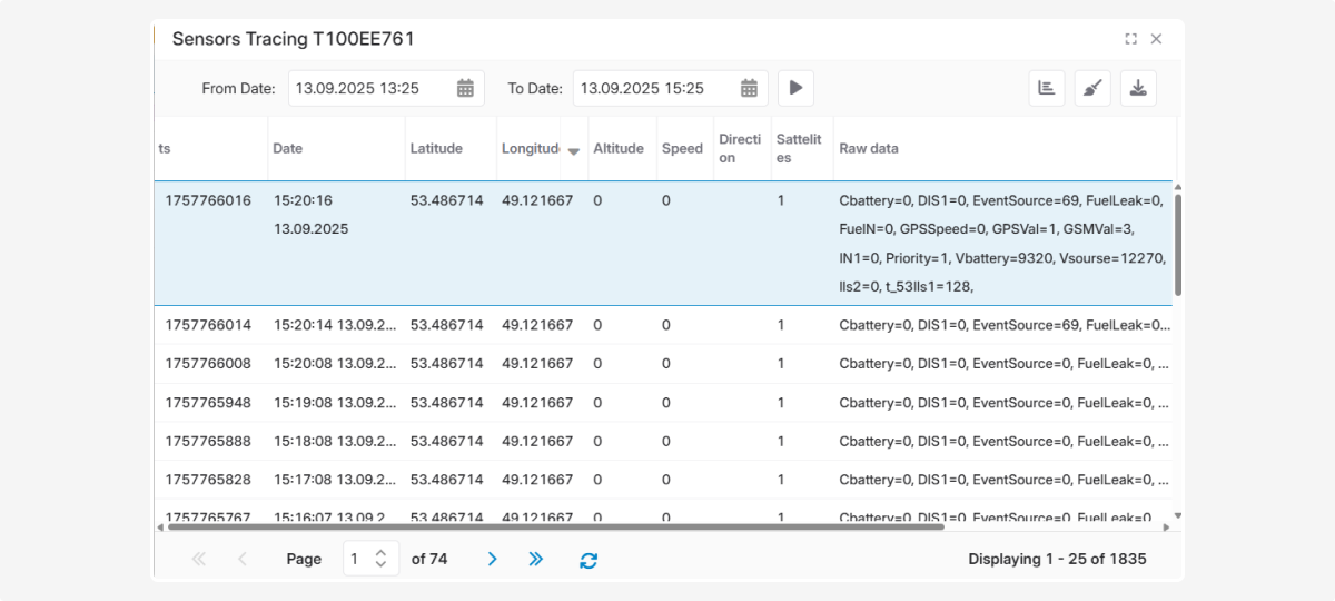
In raw data, the sensor value is: Vsource = 12270
To display the usual reading in volts, the value needs to be divided by 1000.
We can create a handler for this operation and later reuse it with other sensors where values must be divided by 1000.
How to create a handler
-
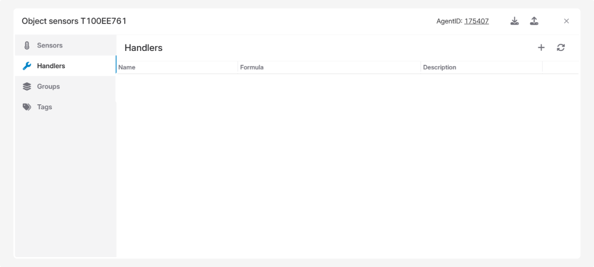
In the Sensors window, open the Handlers tab
-
In the tab, click Add

3. Enter a name for the handler. This name will later be used in the Formula field of the sensor settings. The name can contain only Latin letters, digits, and symbols
4. In the Conversion formula field, write the formula that will use this handler
When referencing a sensor data field, wrap the field name with double percent signs (%%), for example: %fuel_1% or %value%
5. Add a description for the handler so you’ll know what it is used for
6. Click Save
How to configure a calibration table
A handler can include a calibration table that will be applied automatically.
This table helps convert the sensor’s technical readings into understandable values.
Steps:
-
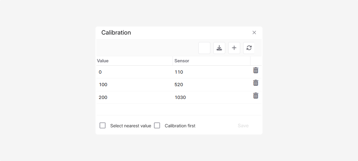
Click the calibration table icon

2. In the calibration table window, click Add 
3. Enter the real value and the corresponding sensor reading
4. Click Save
5. Repeat the process for all required data points
6. Click Save again in the calibration table window
In the calibration table, you can enable the options Select nearest value and Calibration first:
Select nearest value — rounds to the closest calibration point. If the sensor returns a value not exactly listed in the table, the system can either take the nearest point (if enabled) or calculate an intermediate value using the surrounding points (if disabled).
Calibration first — defines how the system processes data during calibration. The system always checks the calibration table first. If an exact value is found in the table — it is used. If not — the system applies the standard calculation algorithm.
You can also use the buttons to upload a calibration table from a file or save it to your computer 

To delete a value from the table, click the delete icon  .
.
How to apply a handler
-
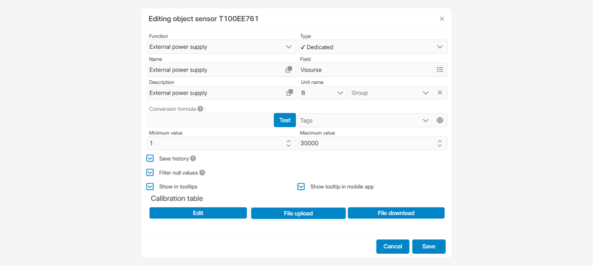
Open the sensor where you want to apply the handler.
2. In the Formula field, enter the handler name: Start with = , then type the handler name. Then in parentheses add the sensor field wrapped in %...%. Example: =divide(%fuel_1%)
3. Test the handler using the Test button
4. Click Save in the sensor settings window to apply the handler.
Examples of using handlers
Example 1. Converting sensor data with a handler
Let’s create a handler:
-
Enter a name — divide
2. In the formula field, enter: %value%/1000
%value% is the raw sensor reading that must be divided by 1000.
3. Add a description — Division by 1000
4. Save the handler

Apply the handler:
-
Open the sensor settings where you want to apply it.
2. In the Formula field, write: =divide(%Vsource%)
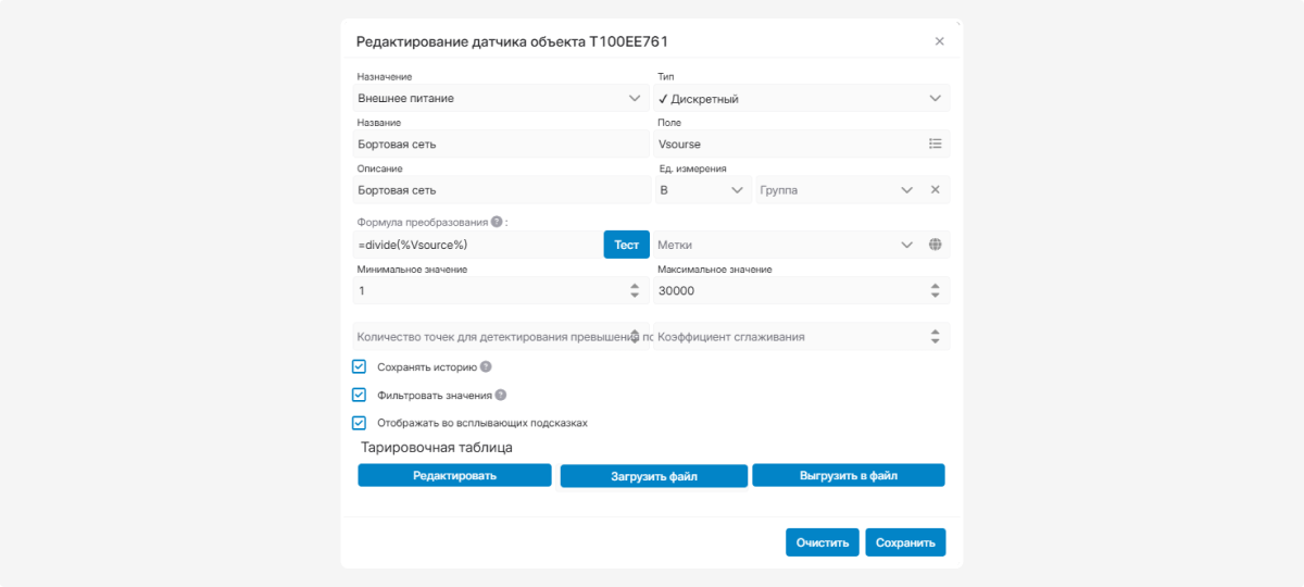
3. Test the handler with the Test button
4. Save the sensor settings
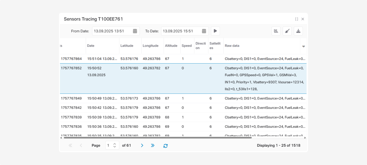
Check the display of sensor readings after applying the handler:
Raw sensor value: Vsource = 12314
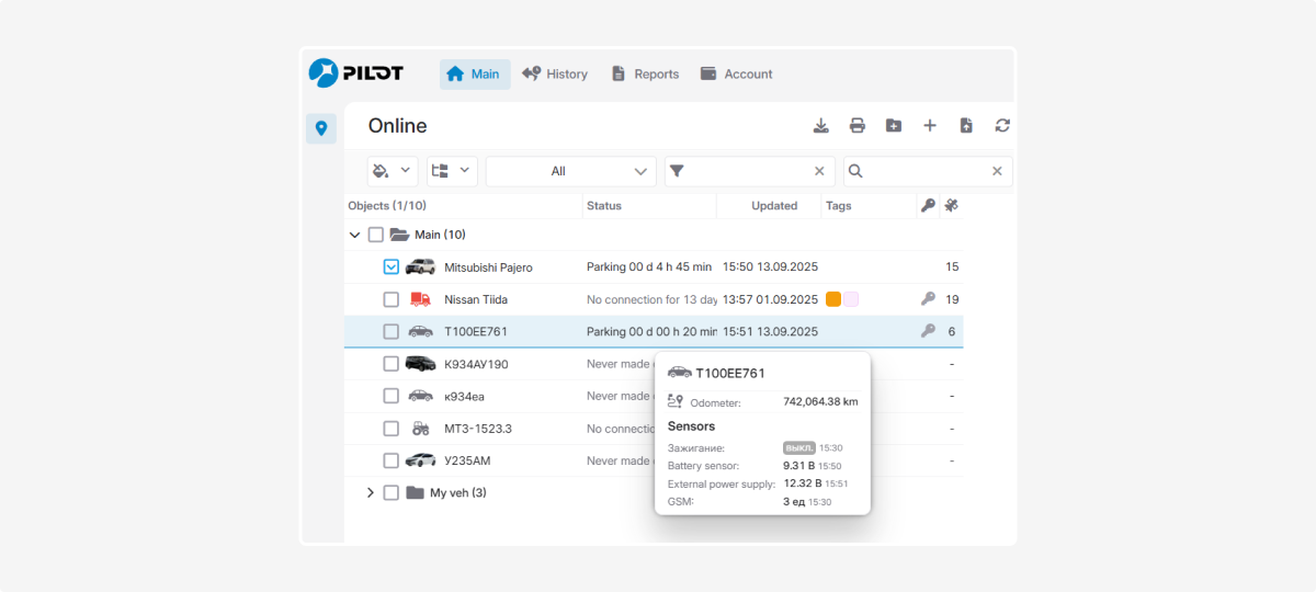
После обработки формулой в подсказке объекта показывается реальное значение датчика — 12,3 В.
This example demonstrates how to perform a simple operation with a handler. However, handlers can also contain more complex formulas if necessary.
Once created, a handler can be reused across multiple similar sensors, helping avoid formula errors.
Example 2. Getting total and average values from two fuel level sensors
Suppose you have two fuel level sensors and you want to see: their total fuel level, and their average fuel level.
Both sensors must output values in the same units, and each must have its own calibration table configured.
|
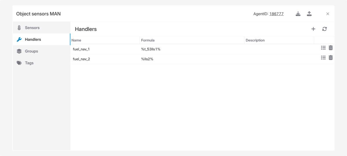
Create handlers for each sensor:
Handler for Sensor 1
-
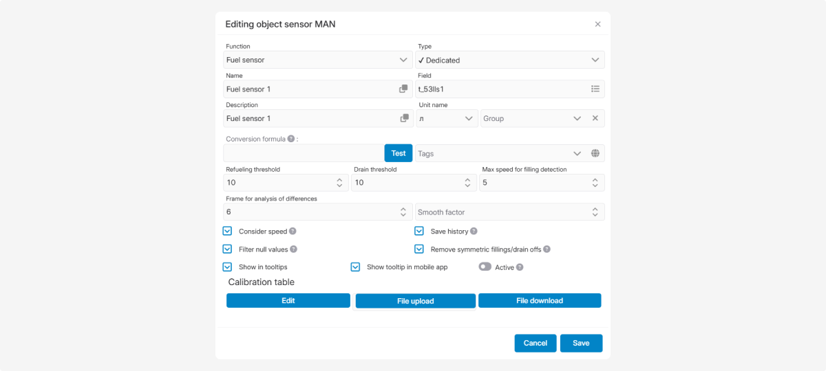
Name: fuel_nav_1
2. Formula: %t_53lls1% (copy the field name from the card of fuel sensor 1)
3. Save the handler
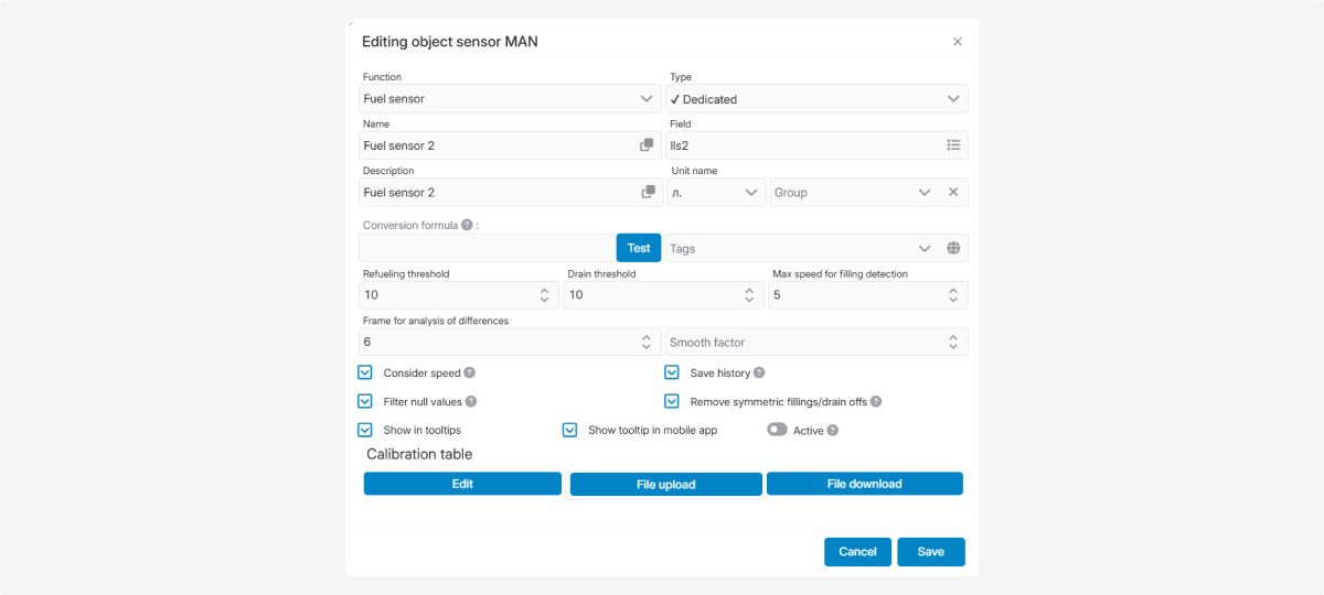
Handler for Sensor 2
-
Name: fuel_nav_2
2. Formula: %lls2% (copy the field name from the card of fuel sensor 2)
3. Save the handler
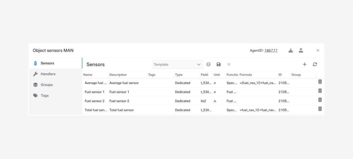
Now create a total fuel sensor
-
Enter name and description — Total fuel sensor
2. Select sensor type — Discrete
3. In the field, specify the stream of one of the sensors (e.g., t_53lls1) — this stream will supply the data points for recalculation.
4. Formula: =fuel_nav_1()+fuel_nav_2()
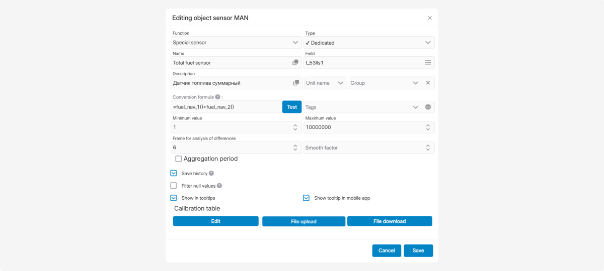
5. Save the total fuel sensor
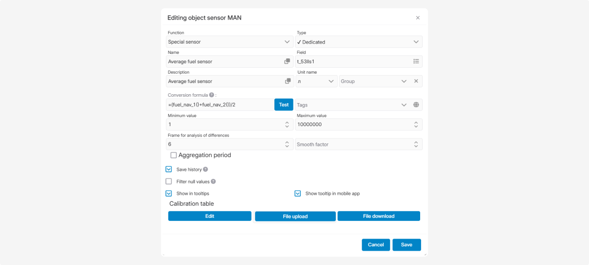
Next, create an average fuel sensor:
-
Enter name and description — Average fuel sensor2. Select sensor type — Discrete3. In the field, specify the stream of one of the sensors (e.g., t_53lls1)4. Formula: =(fuel_nav_1()+fuel_nav_2())/25. Save the average fuel sensor
Check the raw data to verify the new sensor values.
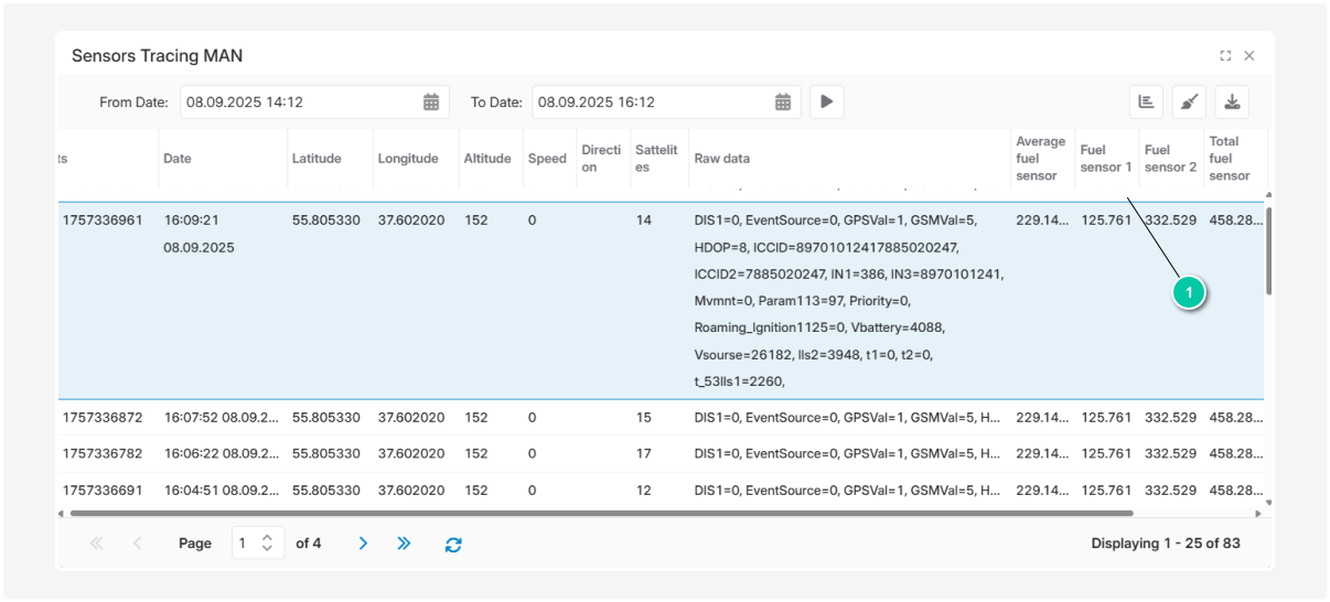
As a result, the object will have four sensors:
-
Fuel sensor 1
-
Fuel sensor 2
-
Total fuel sensor
-
Average fuel sensor
The same approach can be applied to process temperature sensors.